This document is intended to elucidate the basic concept of using the serial port in Max and Arduino. It aims to simplify complex programming techniques, enabling readers to grasp the essence easily and transition seamlessly into more advanced applied programming, building upon the knowledge gained from other available tutorials.
Understanding what we are sending and receiving
First, we need to comprehend what we are actually sending and receiving. Serial communication involves sending and receiving one byte at a time. A byte consists of 8 bits. In decimal, 8 bits can represent a number between 0 and 255. In hexadecimal, it can store values between 0x00 and 0xFF. If represented in binary, it can span from 0b00000000 to 0b11111111. This is a crucial concept because we must manipulate incoming and outgoing bytes.
char, byte and ASCII
Sometimes, you may hear ‘char’ and ‘byte’ used interchangeably, but they are not the same thing. Although they are traditionally the same size (8 bits), they serve different purposes and can be confusing. The ‘char’ type is short for ‘character’ and is a data type that represents a single character of data, such as ‘A’, ‘a’, ‘7’, ‘@’, and so on.
ASCII (American Standard Code for Information Interchange) is a 7-bit character set originally containing 128 characters. However, in modern usage, we commonly refer to extended ASCII, which is an 8-bit character set containing 256 characters, including special characters. For example, if you receive ’65,’ this corresponds to ‘A’ in the ASCII table. When sending ‘A’ over a serial port, you would need to send ’65’ or use the hexadecimal representation ‘0x41’ or the binary representation ‘0b1000001.’
Overall Plan
This code is designed for Arduino Uno, compatible with the Arduino IDE (version 2.2.1). As no special libraries are used, it should work seamlessly with all Arduino boards. Additionally, since we will be utilizing the onboard LED, there is no need to connect any external components.
In essence, when the Arduino board receives a byte of data from Max (or any software or microcontroller) through a serial port, it will alter the timing of blinking the onboard LED. Upon establishing contact and receiving a byte of information, the Arduino will transmit a random number between 65 and 90. As previously discussed, 65 corresponds to ‘A’ in ASCII, and ’90’ corresponds to ‘Z’. In our Max patch, we will observe both the exact byte information and the ASCII converted data.

The ‘incoming’ variable is an integer variable that we will use to store incoming data continuously. The ‘time’ variable is intended to store only the updated date and time for the onboard LED on/off duration. ‘newData’ is a flag variable used to check if the incoming data is new or not. ‘randNum’ is a variable for storing a random number, specifically in our case, it will store ASCII data.
When Arduino is powered up, it begins with the setup() function. The pinMode function is used to set up the built-in LED light. Serial.begin(9600) is for initializing the serial port, and 9600 signifies the baud speed rate of 9600. Then, we proceed to run the establishContact() function as follows:

Arduino has `print`, `println`, and `write` functions to print data to the serial port. `println` and `print` are essentially the same, with the only difference being that `println` adds a line feed at the end, whereas `print` requires the manual inclusion of `(‘\n’)` if you want a new line at the end. Both functions translate the data into human-readable ASCII text. Meanwhile, the `write` function prints binary data to the serial port. In our example, we will use `println` because we will simply use each byte at one time.
First, we print out “<Checking the serial port…>” to indicate that we are starting. Then, the while statement checks if there are a number of bytes available to read. It continuously checks, in this example every 300 milliseconds, to see if there is read data. When data is read, we will finish this function.
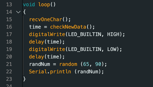
When the `setup()` function is finished, Arduino begins to run the `loop()` function, and as the name of the function implies, this function loops continuously. In the `loop` function, we run the `recvOneChar()` function to get data through the serial port, and then the `checkNewData()` function checks if it is new data. Subsequently, the data is assigned to the `time` variable. Lines 17-20 control the on and off states of the built-in LED based on the duration of the `time` variable (millisecond). After that, we generate a random number between 65 and 90, representing the alphabet A to Z in ASCII, and send it to the serial port using the `Serial.println` function.
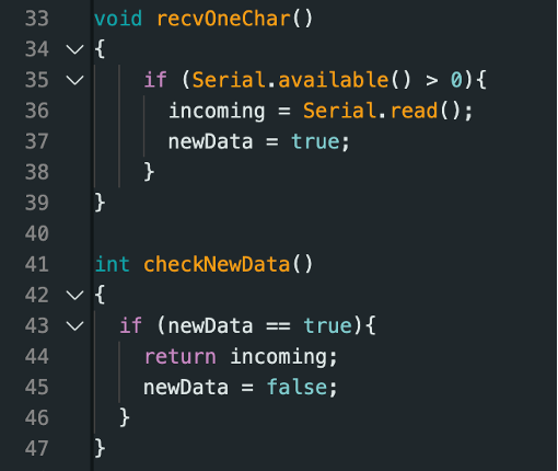
The `recvOneChar()` and `checkNewData()` functions are straightforward, but let’s take a closer look. Here, we again encounter the `Serial.available()` function, which we used in the `setup()` function. One behavior we need to understand about `Serial.available()` is that it continuously returns the number of bytes available to read until we use `Serial.read()` to read the data, as we do here. Once the data is read, unless there is new data, `Serial.available()` will return -1.
Max Patch
This Max patch is quite simple, and it has a single window with a JS window (which pops up when you double-click the ‘js serial.js’ object). Let’s discuss the main patch and then take a look inside the JS patch.
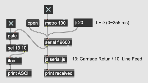
When you click the top toggle box, it enables the metro object, and it sends out a ‘bang’ message every 100 milliseconds. The ‘serial f 9600’ object communicates with the Arduino board. The ‘f’ in the serial object specifies which port the Arduino is using. You may send ‘print’ message to see all the available serial ports, as follows:
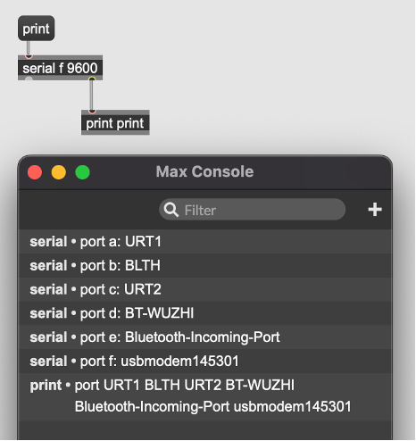
Then, you may check by sending a ‘getport’ message to see what is set:
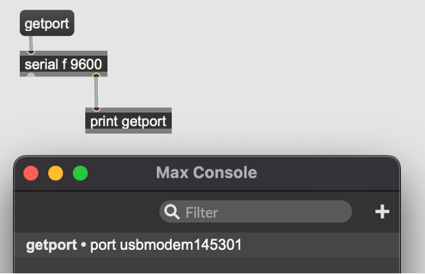
If your Arduino is using a different port like ‘a’ or ‘b’ or anything else, please change it accordingly. Now, adjust the top-right number box labeled ‘LED (0~255 ms).’ In the Max console window, you should see numbers scrolling up. These numbers are generated randomly by your Arduino. Once you spot the Arduino board, observe the built-in LED blinking based on the number you have set (Note: the range is 0-255 milliseconds, meaning the blinking interval cannot be shorter than 0.25 seconds). Click the top-left corner toggle, and you will see ASCII characters associated with the numbers scrolling up.
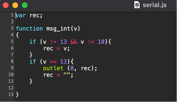
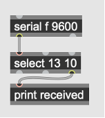
The above is a window that you see when you double-click the js object. The js object loads the serial.js file. This js object receives an argument (inlet) and runs it through the msg_int (v) function. This function essentially filters out carriage return (ASCII Code 13) and line feed (ASCII code 10), and sends out a byte of data we receive to the outlet. This can be done with a select object as follows, but the js object has a lot more powerful features you can use:
Do you have trouble with the Arduino serial terminal?
It’s possible that you are experiencing issues with the Arduino serial terminal or not seeing any input coming into Max. This indicates a potential mistake in your Arduino code or Max patch, or you may be inadvertently trying to use two serial terminals simultaneously. Please understand that you can only connect one device to one serial port. So, if you attempt to connect the Arduino’s serial port simultaneously to both Max and the Arduino serial terminal (which is essentially just another software on your computer), only one of them will work. In our example, if you often use the Arduino serial terminal, you will not see continuous messages in the Max console, as it will be interrupted.
Reply